Overview
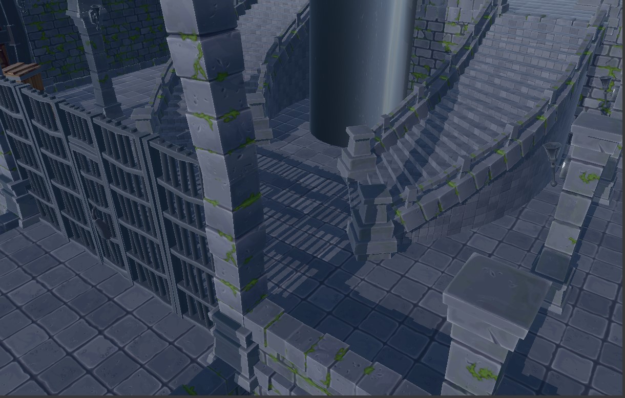
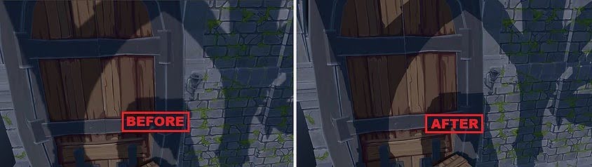
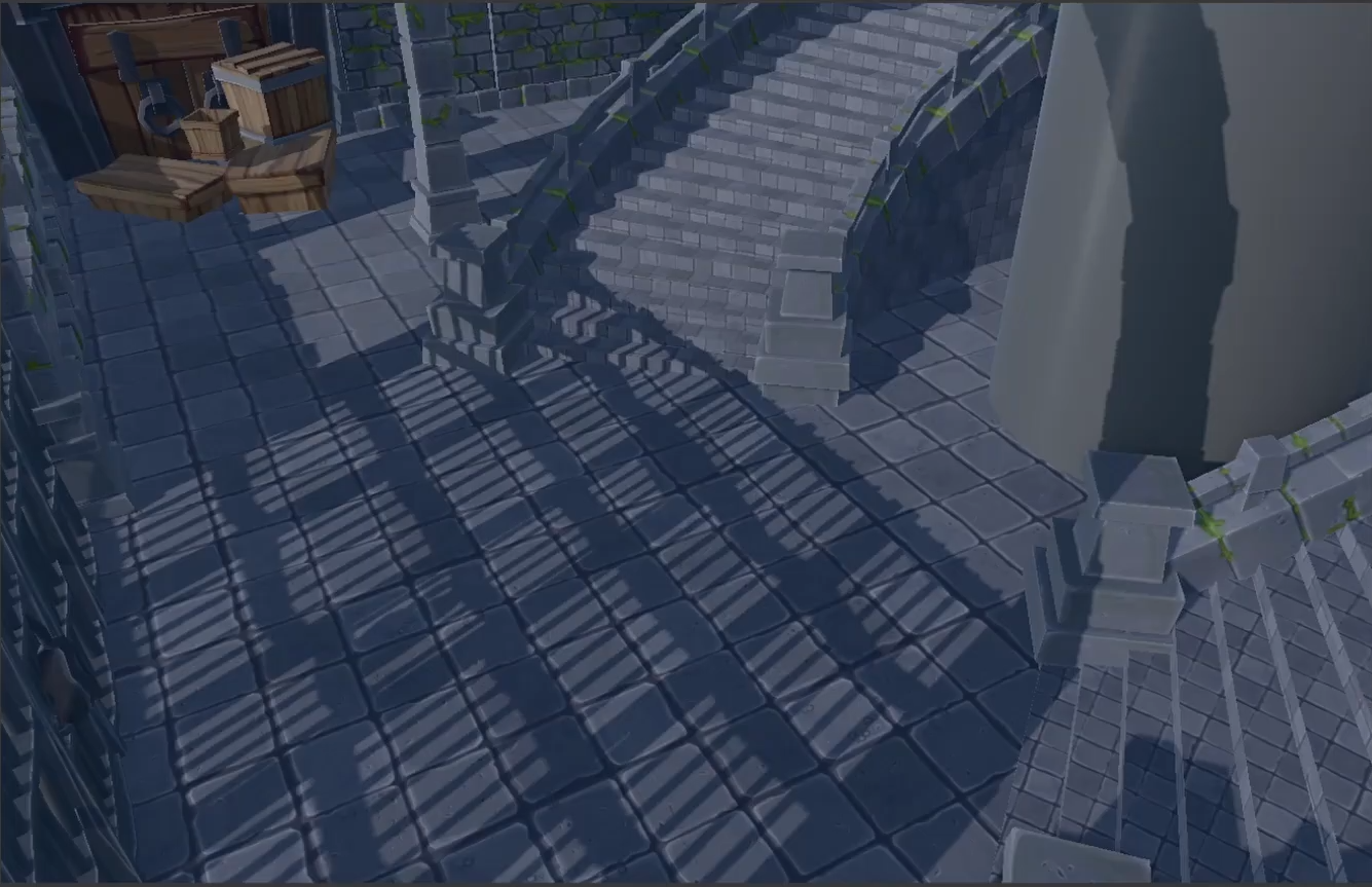
After implementing Depth Buffer Fitting, the directional shadow system was able to concentrate the shadow map around the geometry actually visible by the camera. However, perspective aliasing was still noticeable because a single shadow map distributed the same amount of resolution across the entire visible depth range. Objects close to the camera therefore received the same shadow-map density as distant geometry, even though near shadows require significantly more detail.
Cascaded Shadow Maps were introduced to solve this problem by dividing the visible camera range into several regions and assigning an independent shadow projection to each one.
Supporting Multiple Shadow Projections
With the problem identified, the next step was to extend the shadow-map infrastructure to support multiple independent shadow projections. This required changes to how shadow textures are stored, configured, generated, and rendered across the pipeline.
1. Texture-array support for Shadow Mapping
The texture system was extended to support individual Depth Stencil Views for each slice of a texture array. This allowed the cascaded shadow maps to share a single Texture2DArray, while each cascade could still be independently selected as a depth-rendering target. The existing behaviour for regular 2D depth textures was preserved.
2. Cascade configuration and splitting
Directional-light shadow settings were expanded with a configurable number of cascades, adjustable split positions and two fitting modes: Fit to Scene and Fit to Cascade. These parameters can be modified directly from the editor and are serialized with the light, making the distribution of shadow resolution adaptable to different scenes.
3. GPU cascade-frustum generation
The existing GPU Depth Buffer Fitting stage was extended to generate the light projection for every cascade. The depth-fitted camera range is divided according to the configured split percentages, and each resulting camera sub-frustum is reconstructed independently. A bounding volume is then calculated for each region and used to generate its directional-light orthographic projection, keeping the complete fitting process on the GPU.
4. Cascaded shadow-map rendering
The Shadow Map Pass was adapted to render every cascade into a different slice of the shadow texture array. Static meshes and GPU-skinned animated models continue to use the same shadow-rendering path, while the appropriate cascade matrix and array slice are selected for each shadow pass. PIX captures were also used to verify that each cascade was correctly rendered into its corresponding Texture2DArray slice.
5. Cascade selection during deferred lighting
Deferred lighting was updated to sample the new cascaded shadow texture instead of relying on a single shadow map. For every visible fragment, the shader tests the cascade projections from near to far and selects the first cascade containing that world-space position. The existing shadow bias, strength and PCF filtering remain applied after the correct cascade has been selected.
6. Cascade tint visualization
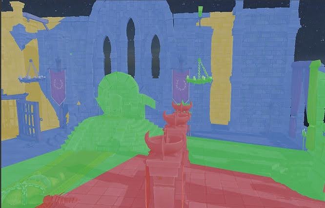
A debug visualization mode was added to make cascade selection immediately visible. Each cascade can tint the affected geometry with a different colour, making it much easier to inspect how the cascade intervals are distributed and how changing the split percentages affects the final result. This visualization is kept separate from the normal rendering behaviour and can be enabled directly from the directional-light shadow settings.
7. Cascade frustum debug drawing
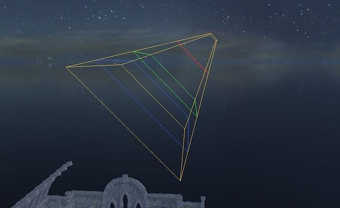
A second debugging tool was implemented to visualize the cascades spatially from the Scene Editor. The depth-fitted Game Camera frustum is divided into its individual cascade sub-frusta and drawn using the same colour convention as the tint visualization. The debug representation reacts to camera movement, cascade count and split configuration, while an asynchronous GPU readback preserves the normal GPU-driven shadow pipeline without introducing a per-frame synchronization stall.
Final Result
A second debugging tool was implemented to visualize the cascades spatially from the Scene Editor. The depth-fitted Game Camera frustum is divided into its individual cascade sub-frusta and drawn using the same colour convention as the tint visualization. The debug representation reacts to camera movement, cascade count and split configuration, while an asynchronous GPU readback preserves the normal GPU-driven shadow pipeline without introducing a per-frame synchronization stall.