Overview
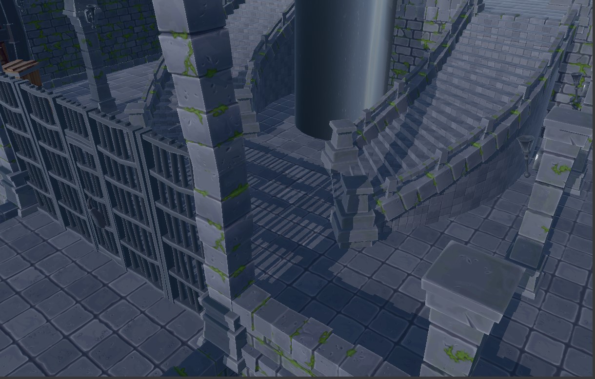
The shadow mapping system was redesigned to use a GPU-driven approach that analyses the camera’s depth buffer and dynamically adjusts the directional light’s orthographic frustum to the geometry actually visible on screen. This replaces the previous bounding-box and CPU-based fitting method, reducing wasted shadow-map space and improving shadow resolution and quality, especially for large environments and distant cameras.
What use to do the Shadow Mapping?
The Shadow Mapping system previously used the bounding boxes of visible meshes to calculate the light’s orthographic frustum. Although this approach worked, it could produce an unnecessarily large approximation, especially when dealing with large geometry such as terrain or open environments. As a result, a significant portion of the shadow map was wasted on empty areas, reducing the effective resolution of the visible shadows.
How does our new Shadow Mapping do?
-
Depth reduction resources. New GPU textures were added to store the minimum and maximum depth values for each region of the image. These textures support both SRV and UAV access, allowing them to be read and written directly by Compute Shaders.
-
Parallel depth-buffer reduction. A new compute pass was implemented to analyse the camera’s real depth buffer. The image is divided into 8×8 pixel groups, and each group calculates its minimum and maximum depth. Using several reduction iterations and two ping-pong textures, these intermediate results are progressively reduced until a single global minimum and maximum depth pair remains.
-
GPU light-frustum generation. The resulting minimum and maximum depth values are converted into view-space distances. These values are then used to reconstruct a tighter camera frustum, calculate its eight corner points, and generate a bounding sphere around the geometry that is actually visible. This sphere is used to build the new orthographic projection for the directional light.
-
Shadow Map Pass adaptation. The Shadow Map Pass was updated to receive the model matrix of each object separately from the GPU-generated lightViewProjection matrix. This allows the same light matrix to be reused for every mesh while preserving correct shadow rendering for both static and GPU-skinned animated models.
-
Render-pipeline integration. The render-pass order was reorganised so that the camera depth buffer is generated before the shadow map. The depth reduction and light-frustum compute passes are then executed, followed by the Shadow Map Pass. The same GPU buffer is used during both shadow-map generation and deferred lighting, avoiding any GPU-to-CPU readback.
-
Removal of the previous fitting method. Once the new system was validated, the bounds-based fitting path and CPU-generated shadow matrices were removed. The related data structures were simplified, and safe fallback behaviour was added for cases where no visible geometry or active shadow-casting directional light is available.
Final Result
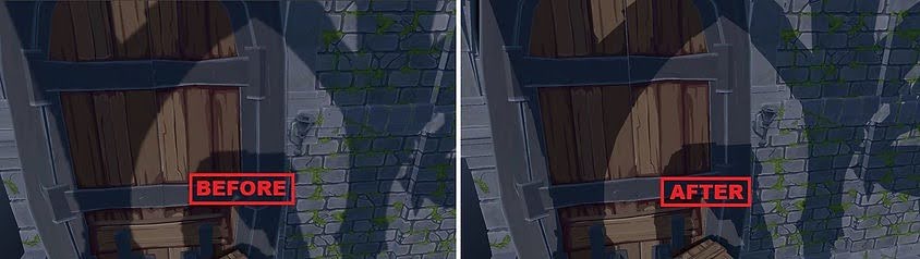
The final result is a light frustum that adapts to the geometry actually visible in each frame and viewport. This makes better use of the available shadow-map resolution, improves shadow definition, and reduces aliasing, particularly in scenes with large meshes or cameras using a distant far plane.