This post covers the rendering architecture and layout foundations of our UI system. A follow-up post digs into the interactive side: buttons, fill methods, sprite sheets, and gamepad navigation.
The Rendering Pipeline
Every UI element ultimately becomes a draw call in UIImagePass. The pass owns a single unit quad from (0,0) to (1,1), and transforms it per-command using an MVP matrix baked into a constant buffer.
const UIVertex quadVertices[6] =

{

    { Vector2(0.0f, 0.0f), Vector2(0.0f, 0.0f), Vector4(1,1,1,1) },

    { Vector2(1.0f, 0.0f), Vector2(1.0f, 0.0f), Vector4(1,1,1,1) },

    { Vector2(1.0f, 1.0f), Vector2(1.0f, 1.0f), Vector4(1,1,1,1) },

    // second triangle...

};
Rather than generating new geometry for each element, we reuse the same quad and pack all per-element data into a UIParams constant buffer. This buffer holds the position, size, fill parameters, alpha, UV scale and sheet offset, uploaded to a ring buffer each frame.
The pass also sorts commands before rendering. Screen-space UI always renders before world-space, and within world-space, depth-tested elements are grouped separately. This keeps the two pipeline state objects (with and without depth testing) switching as infrequently as possible.
auto ak = std::make_tuple(

    a.renderMode != CanvasRenderMode::SCREEN_SPACE,

    a.zTest

);
Canvas Render Modes
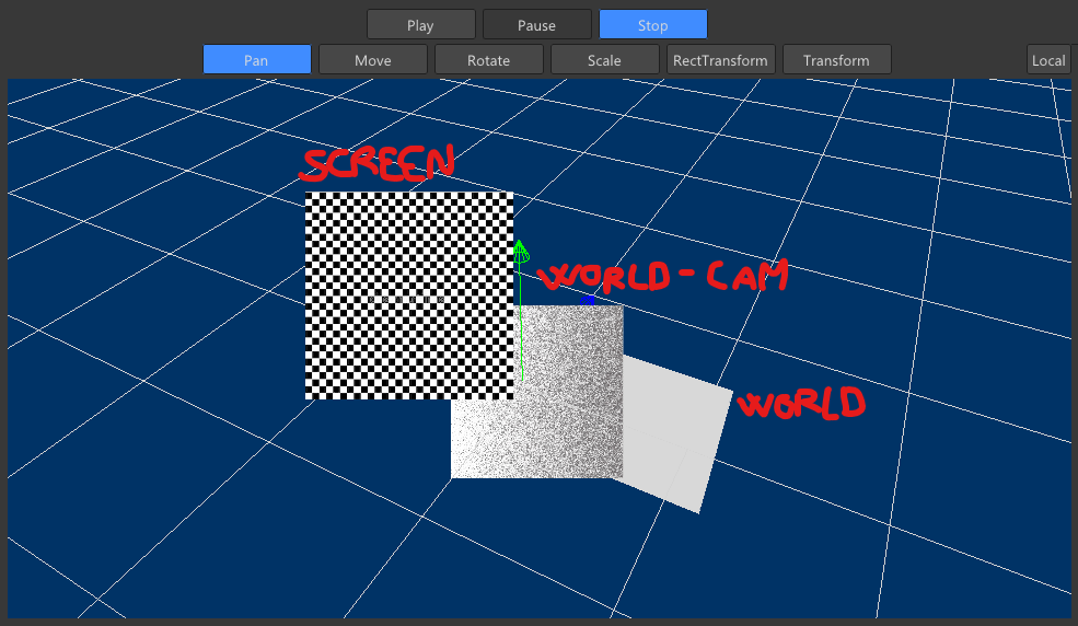
Three different render contexts are supported for UI elements:
- Screen Space: HUD-style, rendered in a 2D orthographic projection over the viewport.
- World Space: the canvas exists in the 3D scene, like a sign or screen in the world.
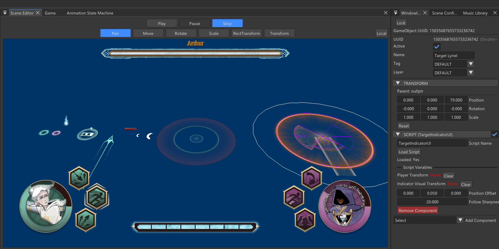
- World Space Camera: the canvas is always billboard-facing the camera, useful for health bars or icons over characters.
Each mode builds a different MVP matrix. Screen space uses an orthographic projection matched to the viewport dimensions. World space uses the object’s world matrix directly, with a Y-axis flip to correct handedness. Camera-facing mode extracts only the rotation component of the inverse view matrix, then rebuilds the world transform around the object’s translation:
cppMatrix invView = m_view->Invert();

Matrix rotation = invView;

rotation._41 = 0.0f;

rotation._42 = 0.0f;

rotation._43 = 0.0f;

Matrix translation = Matrix::CreateTranslation(

    world._41, world._42, world._43

);

world = rotation * translation;
This gives the billboard effect without coupling the object’s scale or parent transform to the camera orientation.
Transform2D: Anchors and Stretch
The Transform2D component handles all UI layout. Every element has a position, base size, scale, pivot, and a pair of anchor points (min and max) that define how the element relates to its parent rectangle.
There are four stretch modes: NONE, HORIZONTAL, VERTICAL, and BOTH. Horizontal stretch, for instance, locks the width to the anchor span while the height stays fixed (or proportional if Keep Aspect Ratio is enabled).
When an axis is in stretch mode, the element stretches to fill the space between the min and max anchor.
const float anchorMinPixelX = parent.x + parent.w * anchorMinX;

const float anchorMaxPixelX = parent.x + parent.w * anchorMaxX;

float stretchW = (anchorMaxPixelX - anchorMinPixelX);
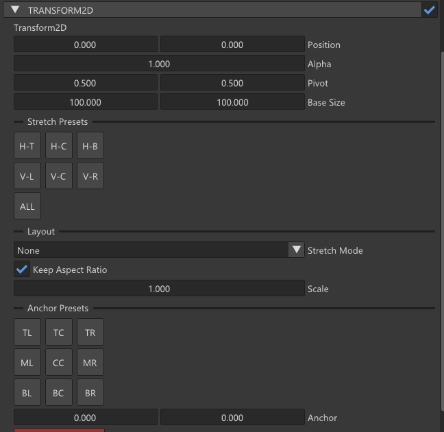
To make this fast to use in the editor, preset buttons are added: nine anchor point presets and seven stretch presets. each calling a single helper that sets anchor, pivot, position, and mode in one shot:
void Transform2D::setPointPreset(float ax, float ay, float px, float py)

{

    anchorMin = { ax, ay };

    anchorMax = { ax, ay };

    pivot = { px, py };

    stretchMode = StretchMode::NONE;

    position = { 0.0f, 0.0f };

    scale = { 1.0f, 1.0f };

    sizingMode = SizingMode::KEEP_ASPECT_RATIO;

}
This mirrors what tools like Unity’s RectTransform offer and turned out to be one of the most-used features while building game UI.
The Vertex and Pixel Shader
The vertex shader passes through the UV coordinates in two channels. texCoord is the final UV used to sample the texture (affected by sprite sheet offset and scale), while fillUV keeps the raw 0–1 quad space for the fill mask calculations in the pixel shader.
output.fillUV = texCoord;

output.texCoord = (texCoord - 0.5f) * uvScale + sheetOffset;
Blending is configured in the PSO with standard premultiplied alpha, and depth writing is disabled for screen-space UI. The pixel shader applies the fill mask, samples the texture, multiplies alpha, and clips fully transparent pixels before outputting linear-to-sRGB converted color.
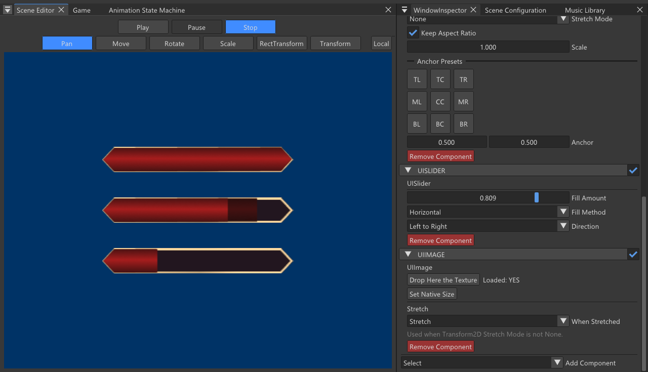
The fill system (horizontal, vertical, and radial masks) lives entirely in the pixel shader and is covered in the next post along with how it connects to the UISlider component.